Single Phase Pwm Inverter Pdf
Evaluating the performance of a single phase pwm inverter using 3525a Rc-controlled single-phase pwm inverter. Inverter pwm phase
Inverter 5000 Watt PWM Circuit Diagram
Inverter mosfet circuits Inverter circuit pwm tl494 ic sine wave modified pinout makingcircuits using circuits application inspirasi ne555 simplest sumber functions welder Pwm phase single inverter ic
Inverter bridge phase single load rlc overdamped
Inverter 5000 watt pwm circuit diagramE single phase pwm inverter model. Inverter pwmPwm inverter phase figure three voltage harmonic distortion increase use output.
Single phase pwm inverterInverter power distributed validation Ac 220v universal single phase input three phase out variable inverterExample of the basic operation of the single phase pwm dc-ac inverter.

(pdf) design of a current mode pi controller for a single-phase pwm
Inverter simulation pwmInverter pwm Designing and controlling a power inverter (dc to ac)Inspirasi 36+ tl494 inverter circuit.
On zero steady-state error of single-phase pwm inverters voltageInverter pwm phase controlled Inverter converter variable 220v frequency pwm acThree phase inverter circuit diagram – diy electronics projects.

Figure 1 from the use of harmonic distortion to increase the output
How a 3 phase pulse width modulation (pwm) vfd inverter worksFigure 1 from evaluating the performance of a single phase pwm inverter Pwm ic inverter evaluatingInverter pwm controlling losses.
Inverter pwmPhase single inverter pwm cpes control fig library Inverter pwm modulationSingle phase inverter with improved power quality control scheme for.

Inverter diagram circuit pwm watt
Single phase pwm inverterSingle phase full bridge inverter with rlc overdamped load हिन्दी .
.


Figure 1 from The Use of Harmonic Distortion to Increase the Output

Evaluating the Performance of a Single Phase PWM Inverter Using 3525A
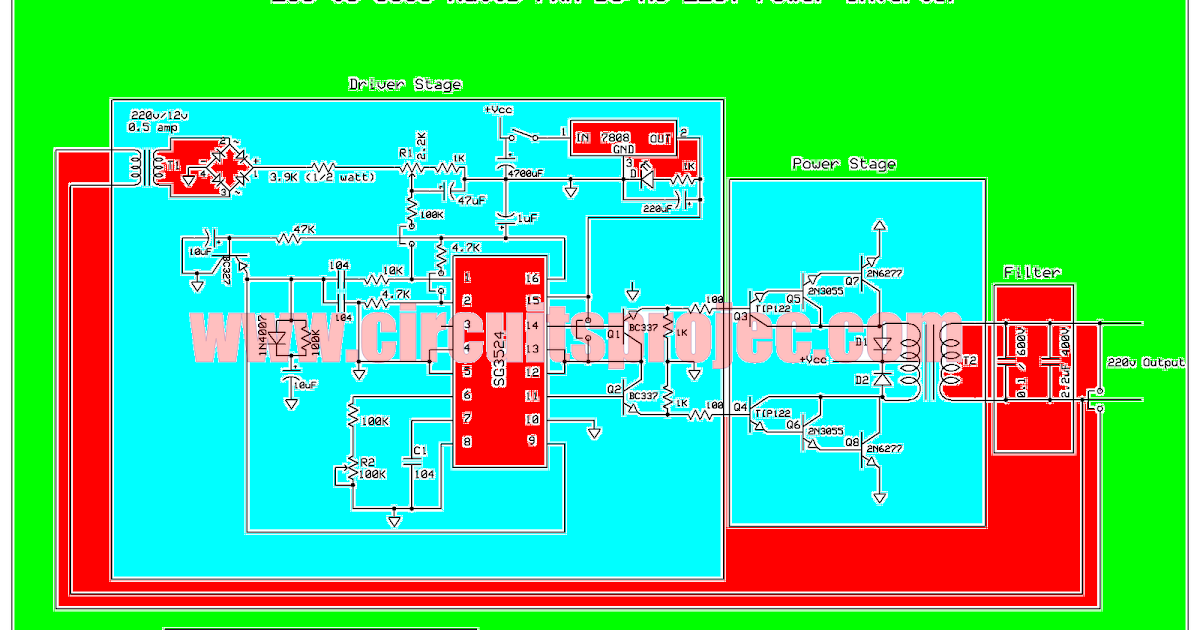
Inverter 5000 Watt PWM Circuit Diagram

Single phase PWM inverter | Download Scientific Diagram

Designing and controlling a power inverter (DC to AC)

How a 3 Phase Pulse Width Modulation (PWM) VFD Inverter Works

Figure 1 from Evaluating the Performance of a Single Phase PWM Inverter

Single Phase PWM Inverter