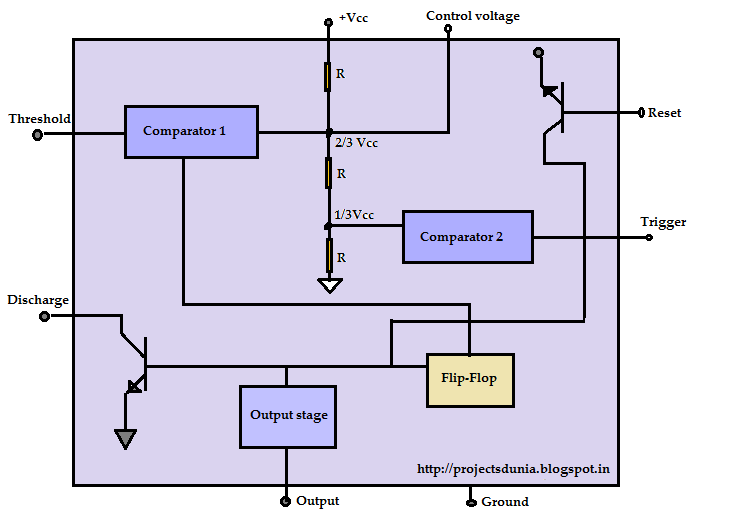
Functional Block Diagram Of 555 Timer
Timer monostable simplified fig 555 diagram block timer ic led flasher electronics wikitechy Ready to help: functional block diagram of ic 555
555 Timer IC: Introduction, Working and Pin configuration | PROJECTSDUNIA
Introduction of 555 timer ic in monostable mode Timer trigger circuit schmitt circuits 555 timer – a complete basic guide
555 diagram block control timer internal theory circuit ic interface engineering
10+ functional block diagram of ic 555How does ne555 timer circuit work 555 timer ic pinout blockIc timer diagram block introduction working configuration.
555 timer diagram block circuit chip does ne555 datasheet inside pinout work works eleccircuit look function willAstable multivibrator using 555 timer 555 timer draws zero off currentGlossary of electronic and engineering terms '555 timer operation'.

The 555 timer schematic diagram
11+ 555 timer diagram555 timer internal diagram block working electrical4u transistors two Ne555 monostable circuits electrical internal ics bistable multivibrator tester mv timing555 timer ic diagram block working functional principle internal circuit schematic comparator avr pic ready help.
555 timer ic555 monostable delay circuitdigest circuits go Ic block diagram timer555 timer ic diagram block basic circuit complete circuits op guide flip tutorial projects flop collection.

555 timer pinout
555 timer ic: introduction, working and pin configuration555 timer led flasher Astable multivibrator using 555 timer555 astable multivibrator timer schematic electrosome.
555 timer functional diagram operation basic555 timer ic diagram block astable multivibrator circuit using internal 555 timer tutorial: how it works and useful example circuits555 timer and 555 timer working.

Ne555 tutorialspoint clap
555 timer ne555 internal dil8 integrated flop circuits zapojenie manuel modes integrado transistor astable comparators temporizador vnútorné minuterie555 ic timer diagram circuit astable description delay pinout pins block multivibrator using time ic555 internal ground circuits functional explain 555 timer block simplified represents circuitry drawsExplain the functional block diagram of timer ic555.
Using the 555 timer ic in special or unusual circuitsSchematic timer Timer 555 ne555 datasheet pinout block ic does eleccircuit flop astable lm555Magicelectronics: block diagram of "555 timer ic".

555 timer ic
555 timer schematic : 555 timer ic working principle block diagramHow does ne555 timer circuit work .
.


Introduction of 555 timer IC in monostable mode

The 555 timer schematic diagram | Download Scientific Diagram

555 timer draws zero off current
555 Timer IC: Introduction, Working and Pin configuration | PROJECTSDUNIA

555 Timer – A Complete Basic Guide | Todays Circuits ~ Engineering

Astable Multivibrator using 555 Timer

10+ Functional Block Diagram Of Ic 555 | Robhosking Diagram